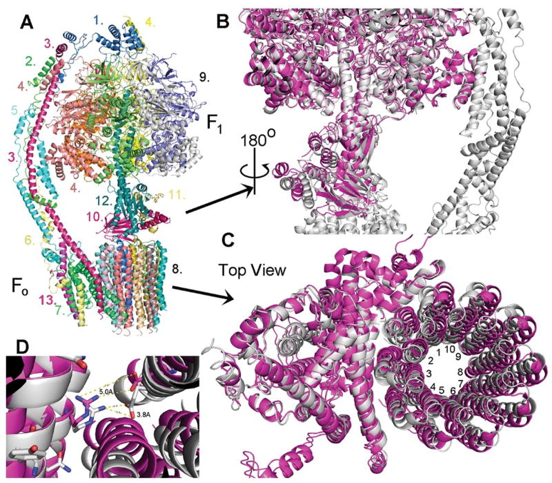
Fig. 3. Overall structure of the yeast ATP synthase.
(A) Molecular model of the F1Fo ATP synthase based on the cryo-EM density map. The subunits are color coded and labeled as: 1. OSCP, 2. F6 3. b-subunit, 4. α-subunit, 5. d-subunit, 6. f-subunit, 7. a-subunit, 8. c10-subunit ring, 9. α3β3 core, 10. δ-subunit, 11. ε-subunit, 12. γ-subunit, 13, i/j-subunit. (B) Superimposition of the crystal structure of the yeast F1 domain (magenta) onto the cryo-EM structure of yeast F1Fo ATP synthase (grey). Three rotor subunits (γ-, δ-, ε-subunits) are displaced by a twisting in the counter clockwise direction. (C) Superimposition of the cryo-EM structure of yeast Fo (magenta, in the absence of F1) on the current structure of F1Fo (grey). The c10-ring is rotated by about 9° in the counter clockwise direction (the direction of ATP synthesis). (D) Relative position of aArg176 and the nearest cGlu59 in the structure of yeast Fo (magenta) and F1Fo (grey). The distance between the side chains of aArg176 and cGlu59 is reduced from about 5.0 Å to about 3.8 Å with the rotation of the c10-ring by 9°.

