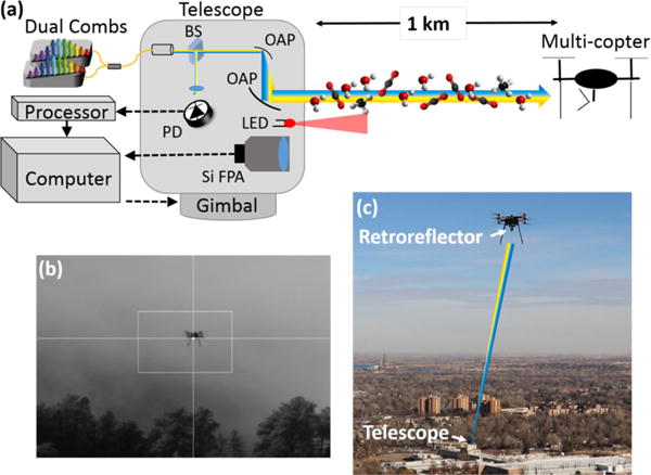
Figure 1.

Setup for DCS to a sUAS. (a) The light from both combs is combined in fiber, then launched from a telescope to a retroreflector on a small multicopter. A co-aligned 850-nm LED and silicon focal plane array (Si FPA) camera are used in the tracking servo to control the azimuth-elevation gimbal. PD: photodetector: BS: beam splitter: OAP: off-axis parabolic mirror (b) Image from Si FPA showing the multi-copter above the tree line. The bright spot is the retroreflected 850 nm LED light. A software feedback loop to the telescope gimbal centers this spot on the cross hairs, which simultaneously maximizes the DCS signal on the photodetector, (c) Photo of the small commercial multi-copter. The dual-comb light is launched from the telescope located in the 1-km distant rooftop laboratory, as indicated.
