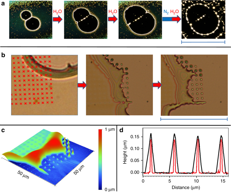
Fig. 6.
Controlled structure formation. a Optical microscopy images (scale bar 430 µm) of a controlled dewetting experiment with a [B12Br12]2−-based layer. Exposure to wet gas induced formation of two neighboring holes that expanded during further exposure to water vapor. The wet gas flow was interrupted to acquire images a1–a3, which immediately stopped growing. Growth of the holes continued when the surface was re-exposed to water vapor. After picture a3 was taken, the surface was stored for one night under nitrogen and again exposed to the wet gas flow. b Optical microscopy images (scale bar=68 µm). Part of the layer containing a growing hole was exposed to a focused electron beam (10 keV, 1.7 nC per irradiated spot) in the vacuum environment of a SEM. The red raster markers indicate the positions of e-beam irradiation. The development of the irradiated surface during further dewetting is shown in the following optical images. c AFM image showing the 3D morphology of the last optical image in b. d AFM line profile over four neighboring tips (short free standing tips in c after the material front has passed (black) and after the surface was sonicated in methanol (red, see details in Supplementary Fig. 29), which dissolves non-irradiated areas of the deposit. The comparison shows that the electron beam induced shape is coated by the moving front of deposited liquid-like material

