Fig. 6.

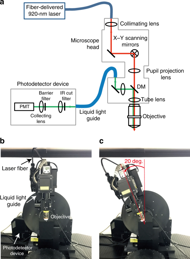
Overview of the two-photon microscope for head-fixed marmosets. a Scheme of the optical pathway. The laser beam was directly introduced to the microscope head with x–y scanners. Thus, the wavefront of the laser at the exit of the objective was not affected by the tilt of the microscope body. The scanners consisted of a resonant mirror and a Galvano mirror. Emitted fluorescence was spilt by a dichromic mirror (DM; reflection and transmission wavelength ranges, 400–755 nm and 800–1300 nm, respectively), introduced to a liquid light guide, filtered by an IR cutting filter (wavelength range, 400–760 nm; 32BA750 RIF, Olympus) and a barrier filter (FV30-FGR), and then collected by a cooled high-sensitivity photomultiplier tube (PMT). b Non-tilt body position of the microscope body. c Body position with a tilt angle of 20° around the front-to-back axis
