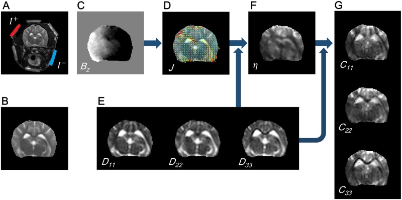
Fig 1. Schematic diagram for DT-J-substitution algorithm.
(A) MR T2-weighted image of the canine head with three pairs of surface electrodes. A current is diagonally injected from the left-top to the right-bottom. (B) MR magnitude image of the brain region. (C) Measured Bz image for the current injection. (D) Recovered projected current flow overlaid on the MR magnitude image. (E) Diagonal components of the estimated diffusion tensor. (F) Recovered scale parameter to connect the conductivity tensor and the diffusion tensor. (G) Recovered electrical conductivity tensor.

