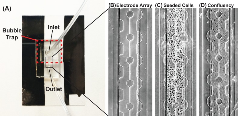
FIG. 2.
The ECIS MBR: (a) Image of the microfluidic device with the embedded electrode array. A bubble trap is fabricated at the inlet port. Gold pads are fabricated onto the ITO pads to allow for soldering, whereby the impedance spectrometer is connected. (b) 2D micrograph of the electrode array. ITO circular pads are connected and centered within the microfluidic device. The counter electrode surrounds the circular pads. (c) Micrograph of HUVEC cells seeded into the microfluidic device. (d) Micrograph of a confluent layer of HUVEC cells on the electrode array after 24 h. Scale bar: 100 μm.

