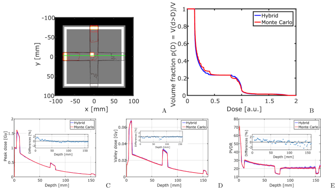
Figure 6.
Cross firing of two microbeam fields in an inhomogeneous phantom. (A) shows how the two fields intersect in the centre of the phantom. (B) is the DVH of the cross firing region within the bone. (C)–(E) show peak dose, valley dose and PVDR dependence on the penetration depth in the phantom for one of the two fields as indicated by the line in figure (A). Small inserts show relative differences between the Monte Carlo and hybrid algorithm.

