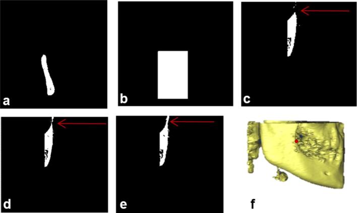
Figure A7.
Detection of landmark R1 (a) initial slice in axial view of volume of interest V2 (b) generated mask (c) coronal slice numbered 1 (d) coronal slice numbered 5 (e) coronal slice numbered 10 (f) R1 landmark on volume V2; (c), (d), (e) are the exemplary slices in coronal view representing the process of detection of R1 landmark. (c) Shows only superior-most point of disconnected point while (d) shows both the disconnected component where a connecting point of inferior-most and superior-most point of two different disconnected components can be detected. (e) Shows the joint between those disconnected components which is desirable for the R1 landmark.

