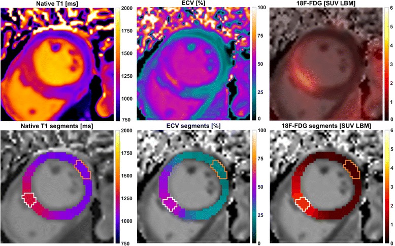
Fig. 1.

Visualization of the three analyzed image signals and their segmentation for one example case. The upper panel shows from left to right: native T1, extracellular volume and 18F-FDG uptake after fusion with the corresponding ECV map. The lower panel shows the respective segmentation results, consisting of 32 segments per slice that are co-localized between the three imaging methods. For each of these, white lines enclose the two sectors with the highest signal and orange lines the sectors defined as remote
