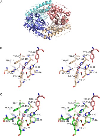
Figure 1.

Structure of MnSOD‐3[Q142H]. A) (top) tetrameric assembly of the four SOD monomeric subunits is formed as a dimer of dimers. Each active dimer is shown in blue (left in top Figure) or red (right in top Figure) and illustrates the proximity of the active sites containing metal ions (purple spheres). The tetrameric interface is formed between the hairpin N domain helices of subunits forming two four‐helix bundles typical of many tetrameric SODs. B) (middle) Stereo diagram of the active site of MnSOD‐3[Q142H] shown in approximately the same orientation and colour as A (top). Tyr 162 is derived from a different subunit and hydrogen bonds with His 30 which then hydrogen bonds to Tyr 34 via a solvent molecule (WAT2; solvent molecules shown as small red spheres). Due to the distance between Tyr 34 and His 142 the hydrogen bonding network is discontinuous, and the latter residue can bind only to WAT1 (the metal‐bound solvent) in this orientation (seen in the X‐ray structure). C) (bottom) The same as Figure B but with the addition of residues from wild‐type MnSOD‐3 shown in green. The proximity of Gln 142 NE2 to His 142 NE2 is illustrated as is the repositioning of Tyr 34. Solvent molecules are illustrated as small green spheres two of which are required to link His 30 to Tyr 34 by hydrogen bonds (H bonds not shown).
