
Figure 4.
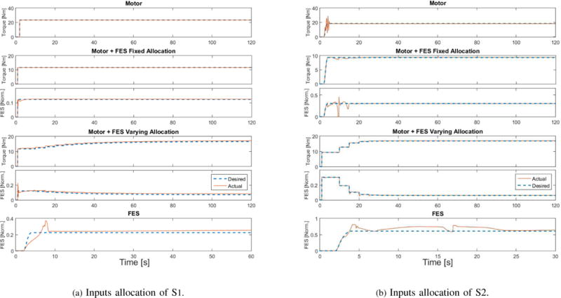
This figure shows the inputs applied to the right leg of S1 and left leg of S2. [Norm.] stands for normalized (no units). The dashed lines stand for desired control inputs, which were computed based on the musculoskeletal parameters as described in Section 4.2.