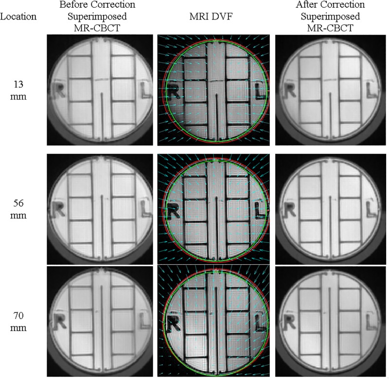
Fig 6. Characterization of magnetic field distortion at 13 mm, 56 mm and 70 mm.
The cyan arrows represent the deformation vector fields (DVF). The red circles correspond to the original outline of the phantom in the MR images before correction, while the green circles correspond to the CBCT outline of the phantom.

