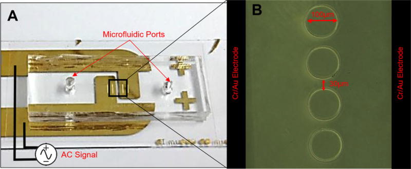
Figure 1.
(A) Top view of the fabricated microfluidic chip and electrodes. The image shows the alignments of the microfluidic device with the DEP pillars positions directly above and in-between the reusable (detachable) electrodes spaced 400 µm. (B) Close-up of the DEP pillars within the microfluidic chip and electrodes that lie below the microfluidic chip and surround the DEP pillars.

