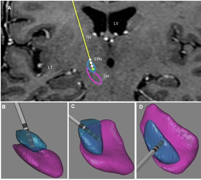
Figure 1.
Illustration of the three-dimensional anatomical location of the electrodes (patient 1). (A) Frontal view of the electrodes (in yellow) with the different contacts (white) and three-dimensional view of STN (in blue), and SNr (in purple). This representation is superimposed on the coronal T2 preoperative MRI of patient 1 to illustrate the location of the STN and SNr. Each electrode had four contacts with the length of 1.5 mm separated by 0.5 mm intervals and numbered from 0 to 3 in the right hemisphere. Contact 0 is the deepest contact (green). (B) Frontal view of the right STN and SNr. (C) Anterolateral view of the right STN and SNr. (D) Superior view of right STN and SNr. In (B–D), the STN and SN were represented in transparency to show the location of the contacts and visualize the “laughter” contact 0 localized within the ventral and medial STN. LV, lateral ventricle; TH, thalamus; TL, temporal lobe.

