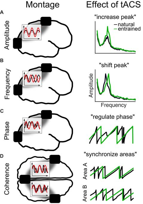
Figure 4.

Different tACS designs and their effects on EEG measures. The left panel shows the electrode montage, simplified electric fields between electrodes (gray) and inlays with the stimulation signal (red) relative to the EEG (black). (A) External current is applied at the natural frequency. As a result in the frequency spectrum, the amplitude of the natural frequency (black) increases due to entrainment (green). (B) Alternating currents is applied at a frequency slightly above the natural frequency. The effect is a shift of the natural frequency to the tACS frequency. (C) Current is applied at the natural frequency. The phase of the natural frequency synchronizes to the phase of tACS and is more regular during stimulation. (D) When three electrodes are used, one can be connected to one pole and the other two to the other pole of the stimulation device. Thereby, the phase underneath the coupled electrodes is the same and areas underneath will synchronize their endogenous phases to the tACS.
