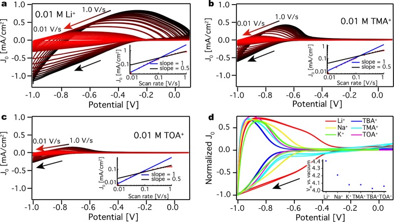
Figure 5.
Cyclic voltammograms
for a ZnO QD film. (a) CVs at different scan
rates in 0.01 M LiClO4 acetonitrile electrolyte solution.
The panel includes a peak current density versus scan rate plot on
a log–log scale. (b) CVs at different scan rates in 0.01 M
TMAPF6 acetonitrile electrolyte solution. The panel includes
a peak current density versus scan rate plot on a log–log scale.
(c) CVs at different scan rates in 0.01 M TOABF4 acetonitrile
electrolyte solution. The panel includes a peak current density versus
scan rate plot on a log–log scale. (d) CVs measured at 0.1
V/s for different electrolyte cations in a 0.1 M acetonitrile electrolyte
solution. The panel includes a plot of the threshold potential versus
vacuum for the different ions. By increasing the size of the electrolyte
cation, charge injection occurs at lower potentials. The scans have
negative direction, indicated by a black arrow, and are repeated three
times for every scan rate. The slope from the insets is given by  , where v stands for the
scan rate and J0 stands for current density.

