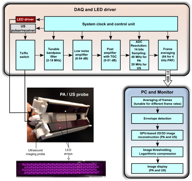
Figure 1.
Block diagram of the light-emitting diode (LED)-based photoacoustic (PA) and ultrasound (US) imaging system. Middle left: photograph of the arrangement of the two LED arrays and the US imaging probe. The two arrays are positioned on both sides of the US imaging probe, angled towards the imaging plane. Bottom left: photograph of an LED array (wavelength: 850 nm). It consists of four rows of 36 LEDs (dimensions: 1 mm × 1 mm). DAQ: data acquisition; Tx: transmit; Rx: receive; TGC: time gain compensation; ADC: analog-to-digital converter; PRF: pulse repetition frequency; USB: universal serial bus; PC: personal computer; GPU: graphics processing unit.

