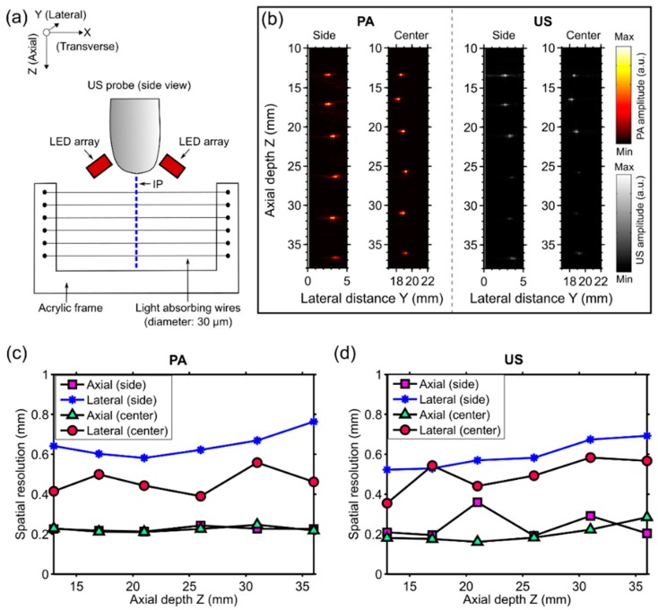
Figure 2.
(a) Schematic illustration of the resolution phantom and the measurement geometry. The phantom, which comprised six light-absorbing wires mounted at different depths (Z) on an acrylic frame, was positioned so that these wires were perpendicular to the imaging plane (IP). LED: light-emitting diode; (b) Photoacoustic (PA) and ultrasound (US) images were acquired with the phantom at two different lateral (Y) positions so that the wires were near the side and the center with respect to the ultrasound imaging probe, respectively. Both PA and US images were displayed in linear scales (a.u.: arbitrary units); (c) Measured axial and lateral PA imaging resolution for the two lateral positions of the phantom (side and center) as a function of depth; and (d) the corresponding values for US imaging.

