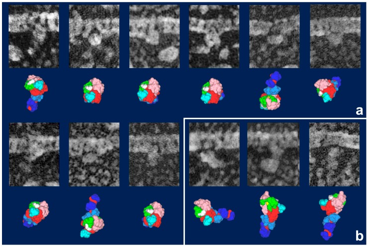
Figure 4.
Gallery of HMM heads attached to actin filaments during sliding, observed in a quick-freeze replica, with the most likely simulation model for each. Model images indicate the best-matched views among the candidate models together with their subdomain arrangement shown as color-coded. (a) Particles judged as in “weakly bound state”. Note that the lever arm portions are not visible in most of the particles. They are hidden beneath an adjacent actin filament or S1’s own body to give globally rounded appearance. The thiol-crosslinked configuration (Figure 3a) is the only model that explains those images. It is also notable that the plane, including upper and lower 50 KDa subdomains, is oriented parallel to the main axis of actin filament, whereas the first actin contact site (yellow patch in Figure 3) is facing the actin side and the second contact site (white patch) is directed to the opposite side, suggesting that these particles are searching for a good clutch site on actin [33]; (b) Particles assigned as Vi-type. Their orientations are variable [18]. Scale bars exhibit 10 nm.

