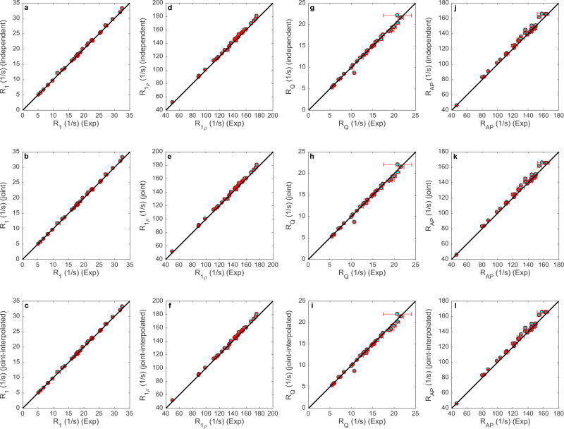
Figure 5.
Back-calculated 700 MHz relaxation rate constants (y-axis) are compared to the experimental results (x-axis). Each row represents a method of spectral density mapping, while each column represents a relaxation rate constant. The relaxation rates of the 32 residues are shown in cyan, while the error bars are depicted in red. The black line represents y=x.

