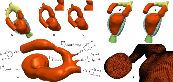
Figure 4.
Processing workflow used for generating blood pool FE models: (A,B) Elements labeled as blood pool or valve were extracted from the mesh used for EM modeling. (C) Surfaces of extracted meshes were smoothed to avoid numerical instabilities due to reentrant corners resulting from a jagged surface. A closeup view of the smoothing effect is displayed in the upper right. The smoothed surface is then used as input for the fluid mesh generation. (D,E) Comparison of the smoothed and unsmoothed blood pool mesh immersed in the original EM mesh. (F) Closeup view of the generated boundary layer mesh. (G) Boundary conditions used for CFD. Moving wall boundary colored in orange, outlet boundaries colored in blue with attached illustration of the 3-element Windkessel models.

