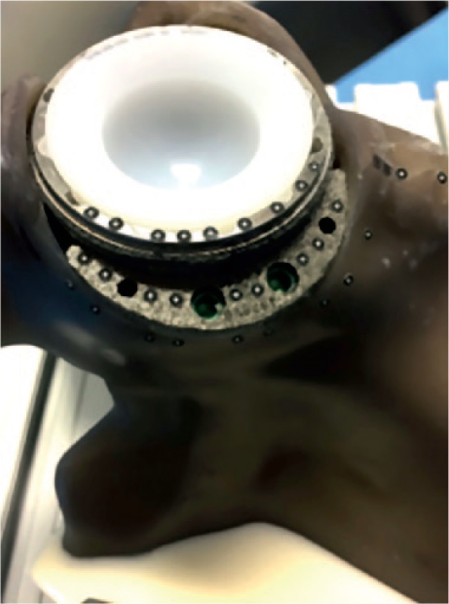
Fig. 4.

Photograph showing an example of optical marker placement on the adjacent surfaces of the respective components; all markers were placed in rows so that each marker had a corresponding marker on the adjacent component to allow for superior discrimination of movement.
