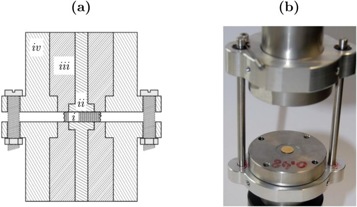
Figure 2.
Sketch (a) and photograph (b) of the cell used for the measurement of bone impedance. The experimental setup is designed to reduce stray capacitance. The bone sample (i) is placed between the two gold electrodes (ii). An insulating Teflon separator (iii) is placed between the measurement electrodes and the stainless steel external shielding (iv). The external shielding of the upper and lower electrodes is connected and grounded.

