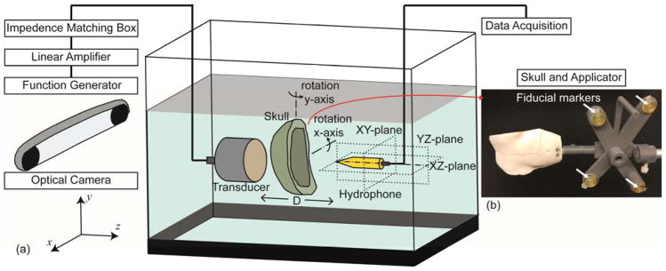
Figure 1.
(a) Schematic of the acoustic field measurement setup in the actual space (not drawn to scale). The transducer was actuated by an electrical signal generated and amplified by a function generator and a linear amplifier, respectively, with impedance matching. Hydrophone scanning was conducted in YZ-, XZ-, XY-planes, and the skull was rotated along each of the x and y axis (0°, ±10° and ±15°). (b) An example of a sheep skull with an applicator. The actual location and orientation of the skull was obtained by an optical tracking system and co-registered to the skull CT data using the coordinate information of the corresponding four fiducial markers indicated with white arrows.

