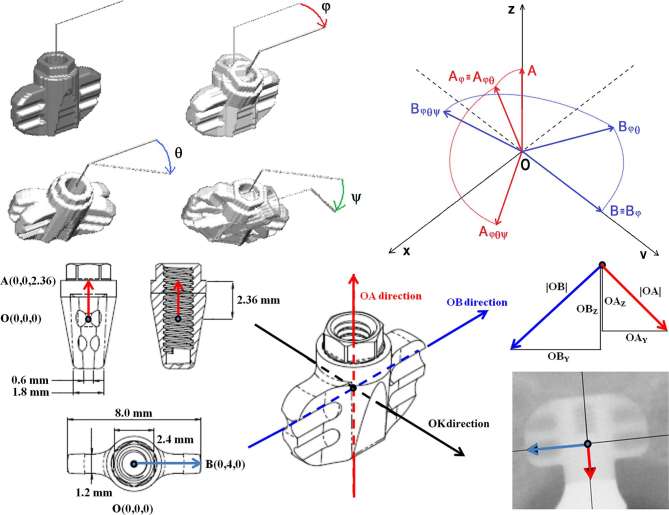
Figure 1.
Pairwise superimposed three-dimensional renderings of the blade by using the three consecutive rotational angles φ, θ and ψ. Drawing of the projection geometry of the points O, A and B during rotations in space. The y- and z-axis of the co-ordinate system represent the horizontal and vertical axis, respectively, of the flat image receptor in which each voxel of the whole-blade phantom will be projected to generate the ghost radiographic image. Project scheme of the blade with size in mm of the body and wings. Three directions: red , blue and black along the three major axes of the blade. Two components of the red vectors and two components of the blue vectors , respectively, along - and -direction (respectively the red and blue arrows in the radiograph) as appearing in a two-dimensional image.

