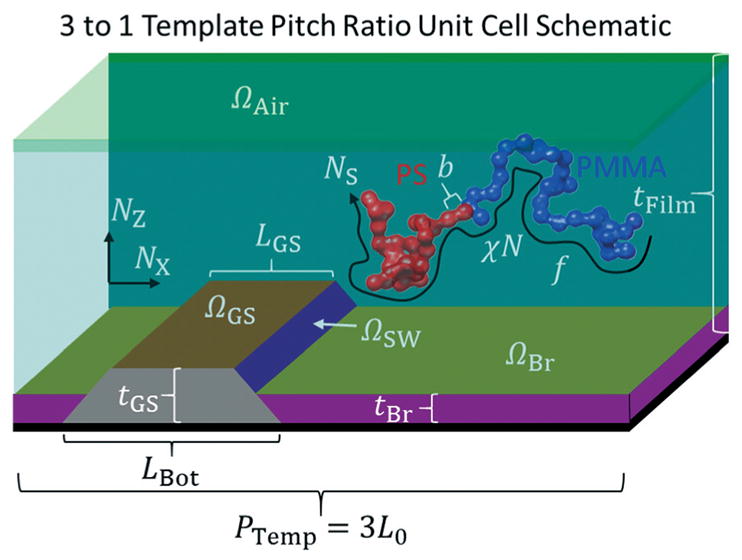
Fig. 2.

Schematic diagram of the boundary conditions used with all possible physical parameters that can be varied in the evolutionary strategy determination of the BCP structure from the CDSAXS measurements. Schematic of unit cell used for DSA templates with a 3 to 1 BCP L0 to template pitch ratio is shown as a 3D cut through for clarity while actual simulations are 2D. Red polymer is PS, blue polymer is PMMA, green top area is the air interface, teal area is where the BCP thin film density fields evolve in the SCFT simulations, olive area is the brush interface, purple area is the brush region, dark orange area is the guide stripe top interface, dark purple area is the guide stripe sidewall, grey area is the guide stripe region, and black area is the substrate. Axes are shown with directions corresponding to the 2D grid discretization.
