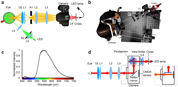
Figure 6.
Experimental setup. (a) Schematic diagram of the system showing the illumination light path, imaging light path, and fixation target placed behind the viewfinder. OL: ophthalmic lens; L1-L6: lenses; A1: circle aperture; A2: annular aperture. (b) Picture showing fundus image was being taken using our prototype system. (c) Spectrum of the LED used for illumination. (d) Schematic diagram showing the light path of the fixation target. Inset shows when capturing the fundus image, the reflex mirror temporarily flips up and the light from the eye reaches the CMOS sensor.

