
Fig. 1. Common tDCS/tACS montages and corresponding simulated electric field distribution.
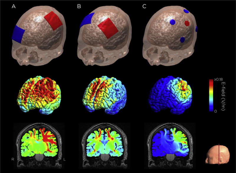
A. M1-SO configuration: Sponge electrodes, one over left primary motor cortex, one over the contralateral supraorbital ridge. B. Bilateral dorsolateral prefrontal cortex configuration: Sponge electrodes over the F3 and F4 EEG sites. C. 4 × 1 HD-tDCS M1 configuration: High-definition electrodes, one over M1, four return electrodes surrounding the center electrode. The electric field was simulated with a current amplitude of 1 mA. Electric field simulation was performed using SimNIBS 2.0.1 [191].