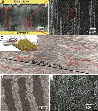
Figure 9.

Unidirectional alignment methods. a) Alignment of CdSe/CdS nanorods by applying an electric field during evaporation of the solution. The red arrow marks the direction of the electric field. b) Higher magnification of the red square in (a), where the individual nanorods are resolved; some are highlighted in red as a guide to the eye (reprinted from Ref. 83 with permission). c) A UHR‐SEM image of a thin film with aligned rods on top, obtained by rubbing with a cloth. The rods clearly demonstrate a preferred orientation along the rubbing direction. Some rods are colored in red as a guide to the eye. Inset: Illustration of the mechanical rubbing process: a rubbing cloth is pressed onto a spin‐coated film; the rotation of the sample in the opposite direction to the rotation of the fibers causes the rods to pile up along the trenches of the fibers, and form ordered arrays of aligned rods (reprinted from Ref. 123 with permission). d) SEM image of aligned CdSe nanorods along a block copolymer domain (reprinted from Ref. 124 with permission). e) SEM image of CdSe/CdS nanorods aligned by applying a voltage while slow evaporation along an interface occurs. In this method, ribbons of NRs oriented parallel to the electric field are obtained (reprinted from Ref. 125 with permission).
