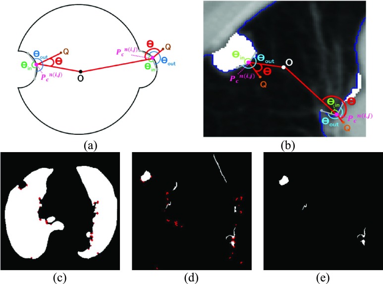
FIGURE 3.
(a) Calculation of the included angle  , and declaration of the point
  to be a concave point if the angle was less than 90°. (b) Angle
  computation examples for the concave point declaration based on the results of Fig. 2(f). (c) Detected concave points with red dots on
  . (d) Detected concave points on the juxta-pleural nodule candidate contours, and (e) the remaining nodule candidates that included any concave point.

