
Figure 2. β1 stabilises voltage dependence of Nav1.7 fast inactivation against mechanical stress.
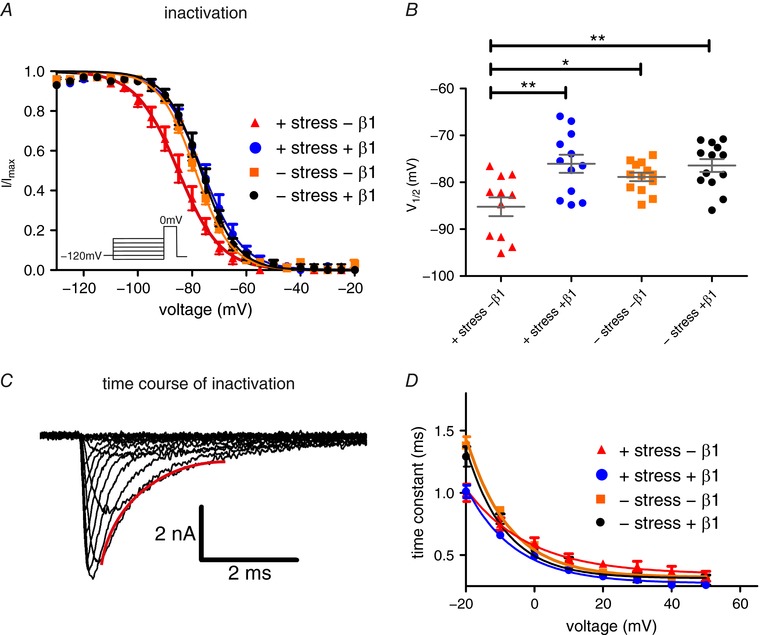
A, voltage dependence of steady‐state fast inactivation with and without β1 expression and exposure to mechanical shear stress. Continuous lines obtained by Boltzmann fits of normalised current–voltage traces. Co‐expression of β1 protects Nav1.7 from a negative shift of fast inactivation induced by mechanical stress. B, values for half‐maximal voltage‐dependent fast inactivation obtained from Boltzmann fits of individual traces. Mean ± SEM values were −85.2 ± 2.0 mV for +shear stress –β1 (red triangles, P = 0.0410 vs. –shear stress –β1, P = 0.0018 vs. –shear stress +β1, P = 0.0014 vs. +shear stress +β1; n = 11), −76.1 ± 1.9 mV for +shear stress +β1 (blue circles, n = 12), −78.9 ± 0.9 mV for –shear stress –β1 (orange squares, n = 13) and −76.4 ± 1.4 mV for –shear stress +β1 (black circles, n = 13). C, a single exponential fit of current decay was used to investigate the time constant of channel inactivation. A representative fit is displayed in red. D, time constant of current decay as obtained by single exponential fits of fast inactivation as shown in C. Mechanical shear stress leads to acceleration of fast inactivation at –20 mV. * P < 0.05; ** P < 0.01 one‐way ANOVA with Bonferroni multiple comparisons test. [Color figure can be viewed at http://wileyonlinelibrary.com]