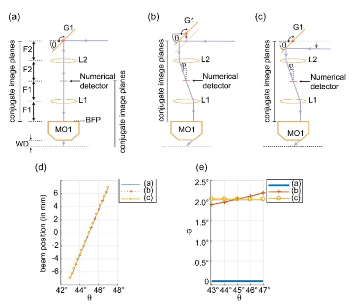
Fig. 2.
Optimization of scanning geometry. (a) Scanning architecture with on-axis excitation beam. (b) Shifting the scan-mirror provides an offset in the incident beam to produce an oblique light-sheet. The point of reflection is centered at back-focal plane of L2 and shifts around it as G1 scans. (c) Shifting of excitation beam from its zero-position (as shown in (a)) to produce desired oblique light-sheet. The point of reflection is no longer centered at back-focal plane of L2 and shifts as G1 scans. (f) Ray-tracing based numerically measured scanned beam-position at the numerical detector plane. (g) Numerically measured scanned beam-tilt at the detection plane.

