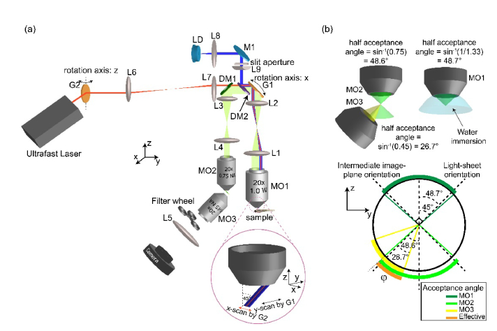
Fig. 3.
SOPi system. (a) Schematic diagram describing the full optical layout of SOPi. Inset shows the scanning arrangement to create and sweep light-sheet in sample volume. MO: microscope objective, DM: dichroic mirror, LD: laser diode, M: mirror. (b) Calculation of effective acceptance angle of SOPi system.

