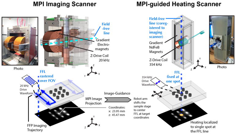
Figure 2.
Hardware setup of the MPI scanner and the image-guided magnetic hyperthermia scanner. Images are first obtained on our Berkeley MPI Scanner (validated in prior work37). To obtain an image, the sensitive field-free-region (FFR) is rastered through a volume. In this study, a field-free-line geometry is used, and images obtained are similar to projection scintigraphy. A separate higher-frequency MPI scanner is used for application of magnetic hyperthermia but has the same geometry, field-free-line. The coordinates are matched to the coordinates of the field-free-line (FFL) of the imaging scanner so as to enable image-guidance from the first scanner. The user is able to pick a target from the image, and the corresponding coordinates on the image is sent to the MPI heating scanner. The robot arm shifts the co-registered animal bed to center the FFL of the heating scanner to the requested coordinates. To locally heat only the target spot, the field-free-line is held in place over the spot while a higher frequency (354kHz) excitation is performed.

