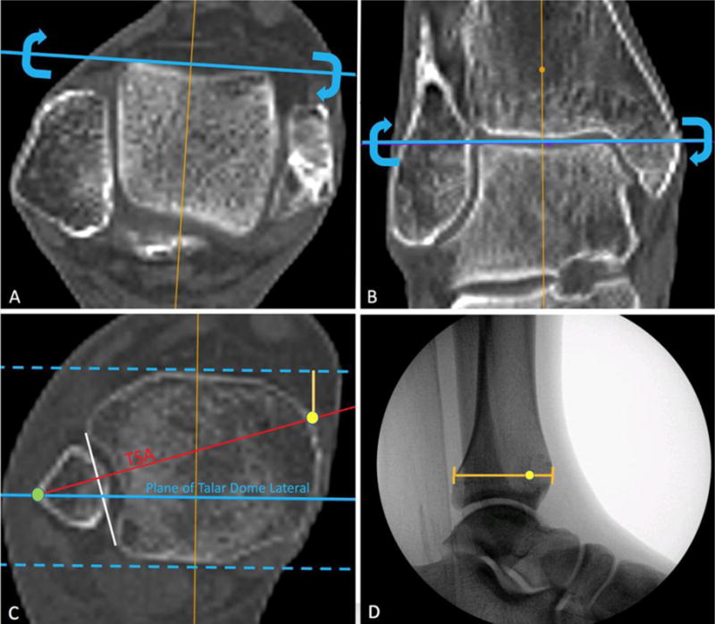
Figure 2.

A. Adjustment of axial CT at the level of the talus such that the localizer line runs tangential to the talar dome. Correction in this plane is equivalent to internal or external rotatory adjustments when obtaining a true talar dome lateral using fluoroscopy. B. Adjustment of coronal CT images such that the localizer line runs tangential to the superior talar dome. Correction in this plane is equivalent to abducting or adducting the lower extremity in the plane of the fluoroscopy machine to eliminate the projection of talar dome double densities. C. Blue dotted lines: Anterior and Posterior cortices as visualized in the lateral projection. Red line: The trans-syndesmotic axis (TSA) which runs perpendicular to a line (white) that is tangential to both the anterior and posterior borders of the incisura. Yellow dot: Templated position of the medial clamp tine Green dot: Templated position of the lateral clamp tine D. True talar dome lateral image with the corresponding location of the yellow dot representing the templated position of the medial clamp tine along the TSA.
