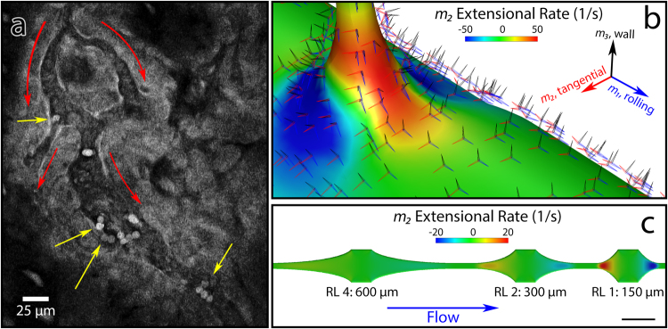
Figure 1.
Mimicry of in vivo extensional stress (a) A snapshot of in vivo two-photon microscopy imaging of inflamed pial vessels in a ubiquitin-GFP mouse (Supplemental Movie 1).  :Flow direction.
  :Stably adherent leukocytes appear to be preferentially located after volume expansions, either at capillary to post-capillary venule (PCV) transition (top left arrow) or at expansions within a vessel (other three arrows). Scale bar: 25 micrometers. (b) Computational fluid dynamics simulation of capillary to PCV transition, demonstrating wall-and-rolling relative tensor basis, and extensional stress incurred as the leukocyte enters the PCV. (c) CFD of biomimetic device that varies extensional stress by varying expansion length, while keeping shear stress equivalent. Scale bar in lower right shows 250 micrometers. Numbers indicate hyperbola lengths, with relative length (RL) = hyperbola length/150 micrometers. A shorter length corresponds to a higher extensional rate.

