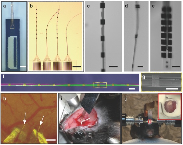
Figure 2.

Implantation of the NET‐e devices. a–e) Photograph of NET‐e devices immersed in water: a) overview of an NET‐e device including the carrier chip and a connector to external I/O mounted atop; b) the e‐beam section of four threads on panel (a) showing the ultraflexibility; c–e) electrodes on c) NET‐e‐l, d) NET‐e‐t, and e) NET‐e‐o. f) Pseudocolor SEM image of an NET‐e‐l device (in purple and gold) attached on a shuttle device made of carbon fiber (purple) with a diameter of 7 µm, showing the small dimension of both. g) Zoom‐in view in panel (f). h) Photograph showing an NET‐e‐o probe successfully delivered into living mouse brain. Arrows denote the delivery entry sites. Dashed lines mark the probe implanted beneath the brain surface. Image was taken 20 d post implantation through a cranial optical window. i) Photograph of a mouse immediately after NET‐e probe implantation. Gently pulling the carrier chip straightened the relaxed section of the probe without pulling out the implanted section. j) Photograph of a head‐constrained mouse on a custom‐built treadmill for awake recording. Scale bars: 2 mm, panel (a); 200 µm, panels (b,h); 20 µm, panels (c–f); and 10 µm, panel (g).
