. 2016 Mar 1;7(6):3862–3868. doi: 10.1039/c5sc04800a

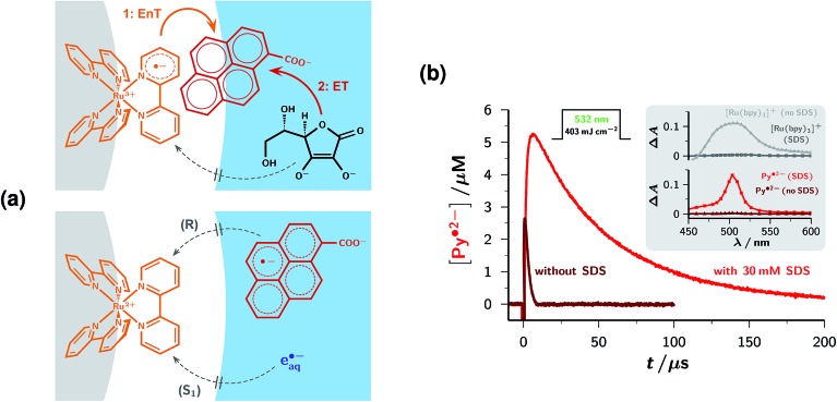
Fig. 3. Optimizing formation and decay of the radical anion Py˙2– by an anionic micelle. (a) Drawn-to-scale pictures of the relevant zones of an SDS micelle (gray, core, radius 19.6 Å; white, Stern layer, diameter 6.8 Å)32 in water (blue) and calculated molecular sizes, illustrating the most probable locations of the reaction partners and intermediates. The light-harvesting complex is attached to the boundary of the micelle core,33,34 and (top) in its excited form 3[Ru(bpy)3]2+ the ligand protruding farthest into the Stern layer has been turned into a radical anion.27 The high dipole moment31 of the redox catalyst Py helps overcome the Coulombic repulsion and enables Py to enter the Stern layer in the orientation shown in the upper drawing, such that it can acquire sufficient orbital overlap with 3[Ru(bpy)3]2+ to undergo the Dexter energy transfer25 EnT. The sacrificial donor Asc2– (top), as well as the delocalized radical anion Py˙2– and the hydrated electron e˙–aq (bottom), can only reside in the aqueous phase. These properties ensure the unhindered sequence of reactions EnT and ET while strongly suppressing the undesired reactions Q, R, and S1 (compare, Fig. 2b and Table 1). (b) Main plot, concentration traces of the electron precursor Py˙2– in deoxygenated homogeneous aqueous solution (brown) and 30 mM aqueous SDS (red) in the photolysis of 6 × 10⁻⁵ M [Ru(bpy)3]2+, 3 × 10⁻⁴ M Py and 1.5 mM Asc2– at pH 12.7 with a single green pulse, intensity given above the traces. The increased yield and much longer life of Py˙2– in the micellar environment are obvious. Inset, transient absorption spectra (top, [Ru(bpy)3]+, gray in water, dark gray in SDS; bottom, Py˙2–, same color coding as in the main plot) at 10 μs after the laser flash and separated by the procedure described in ESI-3.5, demonstrating the practically exclusive presence of [Ru(bpy)3]+ in homogeneous solution and that of Py˙2– in the micellar system. Further information, see text.

Fig. 3