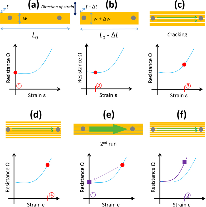
Figure 11.
Probing lines transversally-orientated to the strain using small tipped probes. (a) Zero-strain condition ① and electrical resistance. (b) Small strain condition ② before initial cracking. (c) Initial cracking leads to the appearance of long transversal cracking at higher strain condition ③. (d) High strain condition ④ leads to more cracking. (e) Zero-strain relaxed condition ① following the first strain-sweep and (f) nth sweep strain condition ③ as in (c). The circled numbers refer to specific values of strain. The two probes contact areas are indicated by grey circles.

