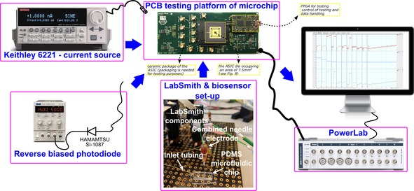
Figure 3.

Illustration of the amperometric tests set‐up, illustrating the three types of test input sources: 1) the Keithley 6221, 2) the dark current of Hamamatsu SI‐1087 and 3) the biosensor. Labsmith is a setup of pumps that can be programmed to control the concentration of the chemical on the microfluiding chip where the biosensor is placed and measures. Powerlab is a data acquisition device by ADInstruments utilised to display the measured signals. The testing PCB (green material/photo on top of the Figure) contains the die of the ASIC (black square dot in the middle of the yellow square), which is packaged (black surrounding the yellow square) to enable and facilitate the testing of the ASIC. Several input/output testing points are shown along with a small size Field Programmable Gate Array (FPGA), which is used for testing and control of the testing purposes(it can be programmed to generate appropriate control signals and to handle the traffic of data).
