Fig. 5.
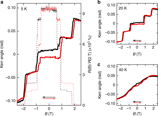
Magneto-optical Kerr effect in few-layer CrI3. a Comparison between the Kerr angle (solid lines, left axis) and the magnetoresistance (dashed lines; data plotted as resistance ratio R(B)/R(2T), right axis) measured on a same device at 5 K. Kerr angle is measured in Faraday geometry with magnetic field applied perpendicular to the plane of CrI3. Black and red curves correspond to sweeping the magnetic field in the direction pointed by the arrows of the corresponding color. The Kerr angle exhibits jumps at magnetic field values that coincide perfectly with the jumps observed in the magnetoresistance. b, c Kerr angle measured at 20 K and 40 K, respectively, as a function of magnetic field. The evolution with temperature is virtually identical to that observed for the magnetoresistance (Fig. 3), with features shifting to lower fields and becoming broader as temperature is increased

