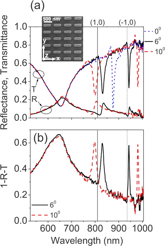
Figure 12.

SLRs in absorption. (a) Measured zero-order transmittance, T, through, and specular reflectance, R, from a plasmonic array of nanoantennas. Data are shown as a function of wavelength for angles of incidence, θ = 6° (black, solid), θ = 10° (red, dashed); transmittance at normal incidence is also shown (blue, dotted). The light was polarized in the y direction, and the wave vector component of the incident wave that was parallel to the array surface is in the x direction. Vertical lines (solid) mark the (+1,0) and (−1,0) diffraction edges at 6°. The inset shows the SEM image of an array of plasmonic nanoantennas. (b) The absorption, as determined using A = 1 – R – T, shown as a function of wavelength for the angles 6° (black, solid) and 10° (red, dashed). Reproduced and adapted with permission from ref (105). Copyright 2009 American Physical Society.
