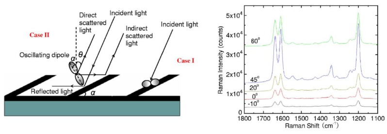
Figure 16.
Left: Schematic illustration of the modified Greenler’s model of an induced dipole on a Ag nanorod: Case I, where the dipole is perpendicular to the incident plane; Case II, where the dipole is on the incident plane. All the induced dipoles are perpendicular to the NR. Right: Representative SERS spectra of trans-1,2-bis(4-pyridyl)-ethene adsorbed on the Ag NR substrate at different incident angles . The peak intensity was strongest at the angle around 45°, which was in agreement with the model. Adapted with permission from [96].

