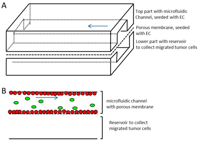
Figure 2.
Schematic representation of the microfluidic device. (A) Upper and lower channel made of Polydimethylsiloxane (PDMS) with porous membrane (pore size 5 µm) sandwiched in between. The upper channel with membrane represents the vessel equivalent (channel dimensions 500 µm × 100 µm × 5.9 cm, width × height × length, respectively) and is seeded with endothelial cells (EC), the lower channel represents reservoir for transmigrating tumor cells (lower channel dimensions 1 mm × 1 mm × 5.9 cm, width x height × length, respectively). (B) Side view sketch of microfluidic channels and membrane separating the two channels. Red dots—endothelial cells growing on all sides of the upper channel and on the membrane; green ovals—tumor cells introduced to vessel equivalent; blue arrow—direction of flow.

