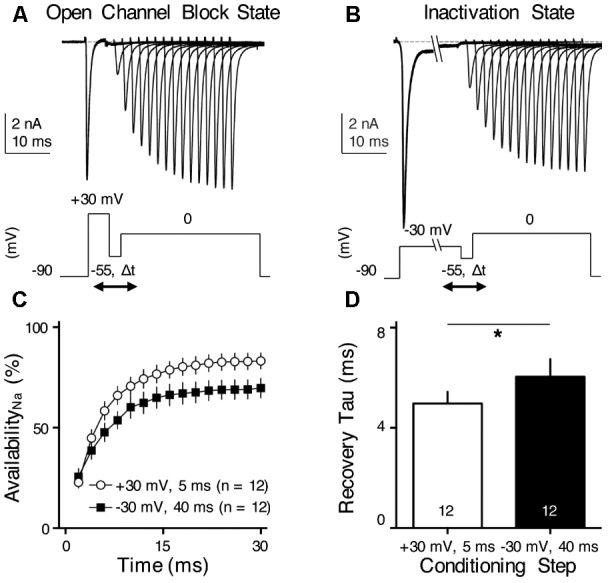
FIGURE 8.

INaR helps increase NaV channel availability and facilitates NaV recovery. (A,B) Representative current traces in response to voltage-clamp protocols shown below traces. The conditioning step is +30 mV for 5 ms in (A) (Open Channel Block State) and –30 mV for 40 ms in (B) (Inactivation State). Δt represents the varying recovery time, increasing from 2 to 30 ms in steps of 2 ms. (C) Population data showing the NaV channel availability (%) as a function of recovery time. In order to calculate NaV channel availability, a reference pulse to 0 mV was applied to NMc neurons (not shown in the figure). The amplitude of recovered NaV current was first adjusted by subtracting the steady-state current that remained at the end of the conditioning step, before being normalized to the reference pulse. The recovery trajectory was fit by a single exponential, in order to obtain recovery time constant (tau) shown in (D). (D) Population data showing the recovery time constant (tau) under two different condition states. Numbers in bars represent sample size. Error bar = standard error. ∗p < 0.05.
