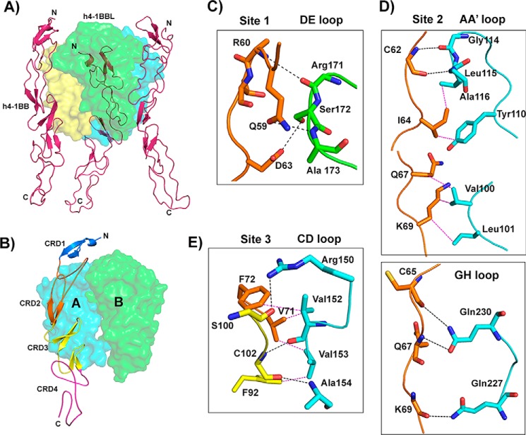
Figure 3.
Crystal structure of the h4-1BB–h4-1BBL complex and binding interface. A, asymmetric unit representing the functional hexameric complex with a h4-1BBL trimer surrounded by three h4-1BB receptors. h4-1BBL is illustrated as a transparent surface in green, cyan, and yellow colors; h4-1BB is shown as a magenta cartoon. B, binding site for each receptor formed by two adjacent protomers of h4-1BBL (surface). Receptor is shown as a cartoon and each CRD is colored separately and marked. C–E, interactions between: residues of the A1 module of h4-1BB CRD2 with the DE loop of h4-1BBL protomer B (C); the long C loop and B2 module of CRD2 (orange) with the AA′ and GH loop of h4-1BBL protomer A (D); and the A2 module of CRD3 with the CD loop of h4-1BBL protomer A (E). In all figures, protomer A is shown in cyan and protomer B in green. All interacting residues are shown as sticks, with CRD2 residues in orange and CRD3 residues in yellow. Hydrogen bonds are represented as black and van der Waals contacts as magenta dashed lines. In C, D, and E, residues of 4-1BB are labeled as single letter amino acids and those of 4-1BBL are marked as three-letter amino acids.

