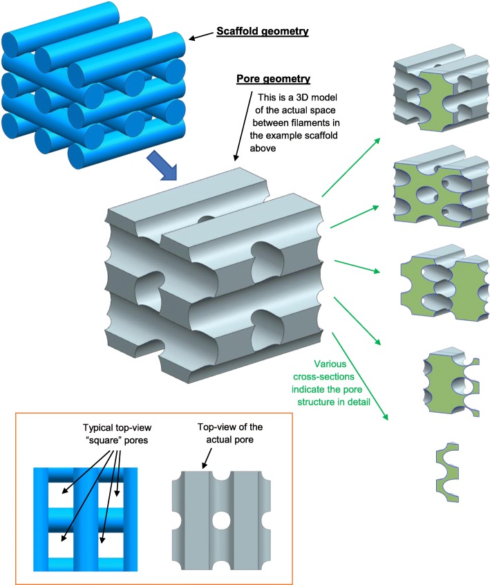
Fig. 6.
An example scaffold was produced in Siemens NX 11 to demonstrate the complex geometry of pores within tissue engineering scaffolds. A 3D CAD model for an example scaffold is shown in the top left. A 3D CAD model for the volume in between the scaffold filaments (i.e. the “pore”) is shown in the centre of the figure. The five-sectioned images to the right show the cross-sectional geometry of the 3D CAD model for the pore. The two images at the bottom-left show top views of the scaffold and pore to illustrate that “square” pores may be seen in microscopy characterisation of scaffolds, but the actual pore does not have a square morphology

