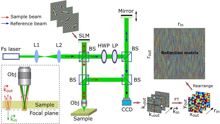
FIG. 1.
Schematic of the experimental setup. The target particle is placed in the focal plane of the incident beam underneath a scattering sample layer. Fs laser, femtosecond pulse laser; L, lens; BS, beam splitter; HWP, half-wave plate; LP, linear polarizer; Obj, objective; SLM, phase-only spatial light modulator (reflection type); CCD, charge-coupled device; FT, Fourier transform; and represent the coordinate values of Fourier spatial frequency of the target area in the focal plane; is the wave vector related to the incident angle of the collimated beam; and are the coordinate integer numbers indicating different lateral positions (scanning points) in the focal plane; and and represent the coordinates in the reflection matrix. Only the phase components are displayed in the measured images and the matrix on the right side.

