
Figure 2.
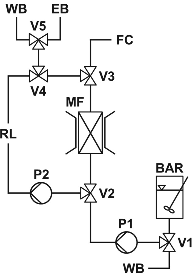
Schematic representation of the HGMF system employed. Key: batch adsorption reactor (BAR); magnetic filter (MF); fraction collector (FC); valves (V1–V5); pumps (P1 & P2); wash buffer (WB); elution buffer (EB).
Official websites use .gov
A
.gov website belongs to an official
government organization in the United States.
Secure .gov websites use HTTPS
A lock (
) or https:// means you've safely
connected to the .gov website. Share sensitive
information only on official, secure websites.
Schematic representation of the HGMF system employed. Key: batch adsorption reactor (BAR); magnetic filter (MF); fraction collector (FC); valves (V1–V5); pumps (P1 & P2); wash buffer (WB); elution buffer (EB).