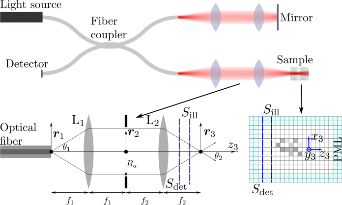
Fig. 1.
Schematic diagram of the modelled OCT system and the model itself. Sill and Sdet represent the planar surfaces upon which the illumination is introduced and the scattered field is detected, respectively. Scattering in free space is simulated by using a perfectly matched layer (PML) which absorbs incident radiation with very low reflection.

